Quantcast
Channel: admin – rtl-sdr.com
Viewing all 2617 articles
Browse latest View live

Soft66IP: Network Connected RTL-SDR with rtl_tcp

$
0
0

Previously from JA7TDO who is a RTL-SDR builder in Japan we’d seen the Soft66RTL and Soft66Q which are both modified RTL-SDR units that are capable of receiving HF as well. To receive HF the Soft66RTL used an upconverter circuit and the newer Soft66Q uses an implementation of the direct sampling mod. Both units come with a preselection filter for the HF bands.

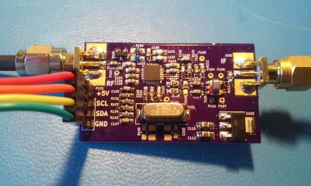
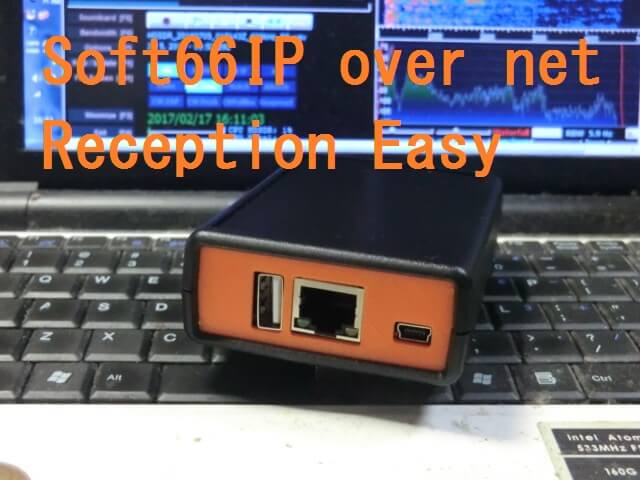
Now JA7TDO has managed to come out with a new modified RTL-SDR which he calls the Soft66IP. The Soft66IP appears to have the same specifications at the Soft66Q except without the additional preselection filter. Instead, its defining feature is that it is built together which what we assume is a Linux enabled wireless router, or some other networked single board PC. This allows you to easily get set up with rtl_tcp for streaming the radio over your network, or the internet. It seems that the unit comes preloaded with the rtl_tcp software installed, making it almost plug and play. JA7TDO advertises the features as:

  • RTL-SDR based
  • 3kHz to 1.7GHz (15MHz to 24MHz is over sampling)
  • 10/100Mbps Ethernet
  • DHCP
  • Wifi(option)
  • cheap price

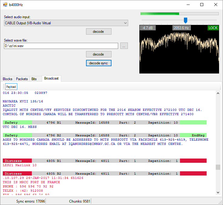
Streaming the radio over a network might be advantageous as it allows you to place the unit near the antenna, avoiding long coax or USB cable runs. But rtl_tcp is quite bandwidth heavy, so it can have trouble streaming at higher sample rates. However, whatever single board PC is used on the Soft66IP may also be capable of running other more efficient streaming software such as OpenWebRX, or more specialized applications such as networked ADS-B decoders as well.

JA7TDO is selling the Soft66IP for a pre-order price of $80 USD which includes worldwide shipping. Shipping starts on March 1. After the pre-order phase the price may rise to $96 USD.

The Soft66IP, networked RTL-SDR.

The post Soft66IP: Network Connected RTL-SDR with rtl_tcp appeared first on rtl-sdr.com.


Searching for giga-Jansky fast radio bursts from the Milky Way with a global array of low-cost radio receivers (RTL-SDRs)

$
0
0

A few days ago a University research paper titled “Searching for giga-Jansky fast radio bursts from the Milky Way with a global array of low-cost radio receivers” was uploaded to the Cornell University Library. In this paper authors Dan Maoz of Tel-Aviv University and Abraham Loeb of Harvard suggest that citizen science enabled mobile phones and RTL-SDR dongles placed around the world could be used to detect fast radio bursts (FRBs) originating from within our own galaxy. The abstract reads:

If fast radio bursts (FRBs) originate from galaxies at cosmological distances, then their all-sky rate implies that the Milky Way may host an FRB on average once every 30-1500 years. If FRBs repeat for decades or centuies, a local FRB could be active now. A typical Galactic FRB would produce a millisecond radio pulse with ~1 GHz flux density of ~3E10 Jy, comparable to the radio flux levels and frequencies of cellular communication devices (cell phones, Wi-Fi, GPS). We propose to search for Galactic FRBs using a global array of low-cost radio receivers. One possibility is to use the ~1GHz communication channel in cellular phones through a Citizens-Science downloadable application. Participating phones would continuously listen for and record candidate FRBs and would periodically upload information to a central data processing website, which correlates the incoming data from all participants, to identify the signature of a real, globe-encompassing, FRB from an astronomical distance. Triangulation of the GPS-based pulse arrival times reported from different locations will provide the FRB sky position, potentially to arc-second accuracy. Pulse arrival times from phones operating at diverse frequencies, or from an on-device de-dispersion search, will yield the dispersion measure (DM) which will indicate the FRB source distance within the Galaxy. A variant of this approach would be to use the built-in ~100 MHz FM-radio receivers present in cell phones for an FRB search at lower frequencies. Alternatively, numerous “software-defined radio” (SDR) devices, costing ~$10 US each, could be plugged into USB ports of personal computers around the world (particularly in radio quiet regions) to establish the global network of receivers.

‘Fast radio bursts’ or FRBs are very brief pulses of extremely strong radio waves which have the transmit power of 500 million suns, though by the time they reach the earth they can only be picked up by radio telescopes. Radio astronomers have so far been mystified by the cause of these FRBs, and research has been hampered by the fact that the source of FRBs is notoriously difficult to pinpoint because they are unpredictable, and their energy appears to originate from all over the sky and not from a single point. Many scientists think that most FRBs must originate from outside of our galaxy, and in 2016 one was finally pinpointed as coming from a dwarf galaxy 2.5 billion light years away from earth. But the authors of the paper speculate from the rate of how often FRBs are seen, that our Milky Way galaxy could host its own local FRB event once every 30 – 1500 years.

If an FRB occurs within our own galaxy then they speculate that the received power could be strong enough to be detected by consumer level mobile phones or RTL-SDR radios, meaning that no large radio telescope dish is required for detection. By continuously monitoring for FRBs on mobile phones and/or RTL-SDRs spread around the world, a local FRB source could one day be pinpointed thanks to the high resolving power of multiple detectors spread apart.

[Also discussed at cfa.harvard.edu/news/2017-07]
The Very Large Array in Mexico was used to pinpoint an FRB in 2016.
Illustration of an FRB. Certain frequencies arrive faster than others.

The post Searching for giga-Jansky fast radio bursts from the Milky Way with a global array of low-cost radio receivers (RTL-SDRs) appeared first on rtl-sdr.com.

Airspy HF+: An upcoming low cost yet high performance HF SDR

$
0
0

Over on the Airspy Yahoo forums and Twitter we’ve seen news of an upcoming new product from the developers of the Airspy SDR. The new product is called the Airspy HF+ and will be a low cost, yet extremely high performance HF specialty radio.

Preliminary specs:

RX range: 0 .. 30 MHz (HF) and 60 – 270 MHz (+)
Architecture: Hybrid (Direct conversion + DDC) using 2 x sigma delta ADC’s @ 36MSPS
Front end: Tracking Filters (all bands), High Dynamic Range LNA’s and Mixers
AGC: Smart AGC controlled by the DSP
DSP: CIC, CFIR and a final (programmable) channel FIR – 18bit resolution
Final bandwidth/resolution after DDC: 18bit @ 600kHz – Scaled and streamed as 16bit
Image rejection: better than 120dBc
Blocking DR: 108 dB
Separate HF and VHF RF inputs – with option to use one multiplexed input if desired
USB 2.0 with Plug and play – No drivers needed
The RF section resides inside a metal shield
Aluminium enclosure about 60 x 100 x 15 mm^3

Basically, this addresses the lack of affordable and good performing receivers for HF and VHF.
Target price < $200

As with all Airspy products the SDR focuses on achieving extremely high dynamic range. From the specs is seems that the dynamic range and image rejection will be high enough so that even extremely strong broadcast AM or FM stations will not require any filtering or attenuation. They are also confident enough to say that no gain sliders will need to ever be adjusted to avoid overload.

For SWLers and MW DXers this seems like the ideal SDR as it should perform as well as high end SDRs like the Perseus, RFSpace and Elad SDRs, but at a fraction of the price.

The product is still in development and no release date has been offered yet, but judging from the Twitter feed the prototype is already working.

The post Airspy HF+: An upcoming low cost yet high performance HF SDR appeared first on rtl-sdr.com.

An RTL-SDR Based Wireless Backscatter Soil Moisture Sensor Network

$
0
0

Recently researcher Spyros Daskalakis wrote in to us and wanted to share his Masters thesis research which is titled ‘Environmental Scatter Radio Sensors with RF Energy Harvesting‘. The research involved creating a low cost, low power (200 microwatt) and yet long range (up to 250m) sensor network for monitoring soil moisture on farms. An RTL-SDR dongle is utilized to receive data from the sensors and MATLAB is used to decode the data.

One interesting innovation is that the sensors transmit data via a backscatter technique which is similar to how RFID tags are read. A carrier emitter is placed in the center of a cluster of sensors and the sensors receive RF bursts from it. The sensor antenna acts as a carrier reflector, and information is modulated onto the reflected signal by changing the antenna-load reflection coefficients according to the sensor reading. This method allows the sensors to only require extremely small amounts of power from a button battery or solar panel in order to transmit at distances of up to 250m. Spyros also proposes using wireless RF energy harvesting techniques which could harvest the electricity needed to power the circuit directly from the carrier emitters or powerful local FM stations.

Spyros’ thesis is available here, and a research paper here.

Backscatter Sensors and RTL-SDR. Received backscatter spectrum.
Backscatter Sensors and RTL-SDR (left). Received backscatter spectrum (right).
https://www.youtube.com/watch?v=_kkxNAqPGqY

The post An RTL-SDR Based Wireless Backscatter Soil Moisture Sensor Network appeared first on rtl-sdr.com.

Video Tutorial: Transmitting Signals with a Raspberry Pi

$
0
0

Over on YouTube Crazy Danish Hacker, who earlier brought us an excellent video tutorial series on GSM sniffing, has now uploaded a two part series that shows how to transmit signals with a Raspberry Pi and the PiFM and RPiTX software. We’ve featured RPiTX several times on this blog before as a cheap TX complement to the RTL-SDR. The software allows you to modulate a GPIO pin on your Raspberry Pi in such a way that it produces AM/FM/SSB etc radio signals at a frequency of choice.

Crazy Danish Hackers tutorial shows us how to set up RPiTX, starting from installing Raspbian and enabling SSH to installing the software and actually transmitting something. Some useful tips to get around common problems are also presented.

http://www.youtube.com/watch?v=mNCKwqKKxyQ
http://www.youtube.com/watch?v=9Vnu-Nl2cX4

The post Video Tutorial: Transmitting Signals with a Raspberry Pi appeared first on rtl-sdr.com.

Reverse Engineering Linear DX Wireless Door Locks

$
0
0

Employees at the network data security company Duo recently had their interest piqued when they discovered that their office’s keycard based door system had a wireless remote which was used by reception to unlock and lock the door. The device was a DX model magnetic lock created by Linear.

After noting down the FCC ID printed on the device, they determined that the operating frequency was 315 MHz. They discovered from the documentation that each wireless DX device is encoded with a unique code that is precoded at the factory. Only remotes with the correct code programmed in can open the door.

The first attack they tried was a simple replay attack. They used a HackRF to record the signal, and then play it back again. This worked perfectly first time.

Next they decided to take this further and reverse engineer the protocol and see if a brute force attack could be applied. By doing some logic analysis on the circuit, they were able to figure out how to iterate over the entire key space. It turns out that the lock can be brute forced in at most 14.5 hours, or 7.25 hours on average.

The Linear DX Wireless Door Lock

The post Reverse Engineering Linear DX Wireless Door Locks appeared first on rtl-sdr.com.

Building an RTL-SDR “Moto Mod”

$
0
0

One nice feature of modern Motorola smartphones is that some models can accept ‘mods’, which are essentially phone cases that snap onto the back of the phone and interface via some exposed data pins. Some examples include a snap on speaker, projector, battery pack and zoom lens. Currently Moto Mods and Indiegogo are running a promotional campaign that gives developers a chance to pitch new Moto Mod ideas to Motorola, and if successful be partnered with Motorola and receive funding to complete and sell the hardware.

Vaclav Bouse is one developer who has been working on an RTL-SDR based Moto Mod. The idea is to integrate RTL-SDR hardware into the Moto Mod phone case form factor and possibly even add transceiver capabilities via an AX5043 transceiver chip. The hardware is still in the very early concept and design phases, and Vaclav is seeking donations on Indiegogo to help fund the development of a prototype (note that donating will not get you the final product). As it will be an RTL-SDR, it should be compatible with all Android RTL-SDR software, such as SDR Touch.

The hardware is also related to his other Moto Mod campaign idea which is a universal remote control.

The Moto Mod RTL-SDR Concept

The post Building an RTL-SDR “Moto Mod” appeared first on rtl-sdr.com.

dumpvdl2: A Lightweight VDL2 Decoder

$
0
0

The VHF Data Link mode 2 (VDL2) is a relatively new wireless transmission mode used on aircraft for sending short messages, position data (similar to ADS-B) and also for allowing traffic controllers to communicate to pilots via text and data. VDL2 is an evolution of ACARS and is eventually supposed to replace it entirely. The advantage over ACARS is that VDL2 can transmit data 10 times faster, and supports a much wider range of services. The main default channel is at 136.975 MHz, but channels could exist on other air band frequencies too.

Over on GitHub Tomasz Lemiech (szpajder – also the author of RTL-Airband) has uploaded a new VDL2 decoder called dumpvdl2. This is a lightweight command line Linux based VDL2 decoder and protocol analyzer. The features include:

  • Runs under Linux (tested on: x86, x86-64, Raspberry Pi)
  • Supports following SDR hardware:
    • RTLSDR (via rtl-sdr library)
    • Mirics SDR (via libmirisdr-4)
    • reads prerecorded IQ data from file
  • Decodes up to 8 VDL2 channels simultaneously
  • Outputs messages to standard output or to a file (with optional daily or hourly file rotation)
  • Outputs ACARS messages to PlanePlotter over UDP/IP socket
  • Supports message filtering by type or direction (uplink, downlink)
  • Outputs decoding statistics using Etsy StatsD protocol

In a previous post we showed how VDL2 could be decoded with MultiPSK on Windows. But the advantage of dumpvdl2 is that it allows you to set up a lightweight monitoring station on something like a Raspberry Pi. dumpvdl2 can also be interfaced with PlanePlotter, and statistics can be graphed with another program such as Grafana.

dumpvdl2 running.
dumpvdl2 running.

The post dumpvdl2: A Lightweight VDL2 Decoder appeared first on rtl-sdr.com.


RTL-SDR Tutorial: GPS Decoding and Plotting

$
0
0

The RTL-SDR can be used to receive, decode and plot Global Positioning System (GPS) data in real time. To do this the RTL-SDR must be connected to a GPS antenna.

Extremely cheap $5 or less active GPS antennas with SMA connectors can be found on eBay, Amazon or Aliexpress. These GPS antennas contain a small ceramic patch antenna, a low noise amplifier and a GPS filter. In order to power the LNA in the antenna, you’ll need to have an RTL-SDR with bias tee. Our RTL-SDR.com V3 dongles have this feature built in, but if you don’t have a V3 you could also use a homebrew 5V external bias tee module or hack it into a standard RTL-SDR if you desired.

Also note that most standard R820T/2 RTL-SDRs fail to receive after a few minutes at frequencies above about 1.3 GHz due to heat issues. Our RTL-SDR.com V3 dongles don’t have this problem in most climates thanks to the metal case cooling and improved thermal design on the PCB. If you experience this problem it can also be alleviated by using the special L-Band RTL-SDR drivers.

A typical $3 GPS antenna

The main GPS frequency is 1.575420 GHz, but most of this signal is very weak and below the noise floor. If you were try to view the spectrum of GPS in SDR# you will find that you won’t see much other than perhaps a very weak hump. Only through clever signal processing is such a weak signal actually recovered. Below we show screenshots of the GPS spectrum as seen by an RTL-SDR and more wideband Airspy R2 SDR.

http://GPS%20RTL-SDR

GPS RTL-SDR

http://GPS%20Airspy

GPS Airspy

The following tutorial shows how to receive and decode GPS signals and get a coordinate on a map of your location, using only an RTL-SDR dongle (with bias tee) and GPS antenna. This tutorial is based heavily on Philip Hahn’s blog post at sdrgps.blogspot.com/2015/12/first-proof-of-concept-gps-fix-in.html.

  1. Download GNSS-SDRLIB from github.com/taroz/GNSS-SDRLIB. On GitHub click on the green “Clone or download” button on the right and then click “Download ZIP”. Extract the zip file into a convenient folder on your PC. If you want to use the modified L-band drivers, copy the modified rtlsdr.dll into the the bin folder.
     
  2. Download the latest version of RTK-NAVI from rtklib.com. If you like, you can also try their beta version at github.com/tomojitakasu/RTKLIB_bin/tree/rtklib_2.4.3. Extract the zip into a convenient folder on your PC.
     
  3. Make sure your RTL-SDR is plugged in, and that the bias tee has been activated (V3 software for activating the bias tee, see feature 2).
     
  4. In the GNSS-SDRLIB folder, open gnss-sdrgui.exe. This will be stored in the bin subfolder.
     
  5. Now set the following parameters:
    1. Change the Input Type to RTL-SDR
    2. Place a check next to RTCM MSM , and set the Port to 9999.
    3. Ensure that “Output Interval” is set to 10Hz.
    4. Ensure that “Plot Acquisition” and “Plot Tracking” are both checked.
    5. Under “MISC” optionally enter your approximate latitude and longitude to help with getting an initial lock..
    6. Under the GPS, GLONASS and Galileo headings ensure that the “ALL”
Apply appropriate settings in GNSS-SDRLIB GUI
  1. Press Start. A bunch of command windows will begin opening and closing for a few seconds. After that, a bunch of gnuplot graph windows will open up. These can be ignored.
     
  2. Next go to the extracted RTK-NAVI folder, and enter the bin directory. Open the rtlnavi.exe file.
     
  3. Click on the “I” button in the upper right region.
     
  4. Place a check mark next to (1) Rover, and change the “Type” to TCP Client, and the “Format” to RTCM3. Click on the button with three dots under the leftmost “Opt” and set the “TCP Server Address” to localhost, and the “Port” to 9999. Press the OK button to exit the two windows.
Set the input stream
  1. Now press Start in RTK-NAVI.
     
  2. You should now see several bars in the top graph. These bars show GPS signal strengths for satellites. After a short time you should see a solution in the left panel which will be your current coordinates. If no solution ever comes, try respositioning your GPS antenna for a better view of the sky, and double checking that the bias tee is activated. Sometimes simply restarting GNSS-SDRLIB can fix no solution being found.
Check reception and wait for GPS lock solution.
  1. In RTK-NAVI click on the “Plot” button. This will open a positional plot of the recorded coordinates. To view your position on a Google map, click View → Google Map View. If everything is working correctly you should now be seeing an accurate marker of your current location.
View your GPS position on a map.

The post RTL-SDR Tutorial: GPS Decoding and Plotting appeared first on rtl-sdr.com.

Simple NOAA/Meteor Weather Satellite Antenna: A 137 MHz V-Dipole

$
0
0

Over on his blog Adam 9A4QV (seller of various RTL-SDR related goods including the LNA4ALL) has just made a post detailing a build of a high performance super simple NOAA/Meteor M2 weather satellite antenna. Most antenna designs for polar orbiting weather spacecraft are based on circularly polarized turnstile or QFH designs. However, Adams antenna is based on a very simple linearly polarized dipole, which makes construction almost trivial.

The idea is that by arranging a dipole into a horizontal ‘V’ shape, the radiation pattern will be directed skywards in a figure 0 (zero) pattern. This will be optimal for satellites travelling in front, above and behind the antenna. Since polar orbiting satellites always travel North to South or vice versa, we can take advantage of this fact simply by orienting the antenna North/South. 

There is also another advantage to Adams design. Since the antenna is horizontally polarized, all vertically polarized terrestrial signals will be reduced by 20 dB. Most terrestrial signals are broadcast in vertical polarization, so this can help significantly reduce interference and overloading on your RTL-SDR. Overloading is a big problem for many trying to receive weather satellites as they transmit at 137 MHz, which is close to the very powerful FM broadcast band, air band, pagers and business radio. In contrast a circularly polarized antenna like a QFH or turnstile only reduces vertically polarized terrestrial signals by 3 dB.

As the satellites broadcast in circular polarization there will be a 3 dB loss in Adams design from using a linear polarized antenna. But this can be considered as almost negligible. Adam also argues that the home construction of a QFH can never be perfect, so there will always be at least a ~1dB loss from inaccurate construction of these antennas anyway.

The final advantage to Adams design is that construction is extremely simple. Just connect one element to the center coax conductor, and the other to the shield, and spread apart by 120 degrees.

Adam 9A4QV's V-Dipole for 137 MHz Weather Satellites.
Adam 9A4QV’s V-Dipole for 137 MHz Weather Satellites.

Adam has tested the antenna and has gotten excellent results. If you want more information about the antenna design, Adam has also uploaded a pdf with a more indepth description of the design and his thoughts.

http://www.youtube.com/watch?v=9WNmhfpWxdk
http://www.youtube.com/watch?v=oGPamyfhORE

The post Simple NOAA/Meteor Weather Satellite Antenna: A 137 MHz V-Dipole appeared first on rtl-sdr.com.

The Panoradio: A tech-demo for direct sampling SDR

$
0
0

SDR researcher Stefan Scholl (DC9ST) recently wrote in to us and wanted to share his project which is a direct sampling SDR using a fast AD converter on the Zynq SoC (System on Chip). He calls the SDR ‘Panoradio’. He writes:

The Panoradio is a modern software defined radio receiver, that directly samples the antenna signal with 250 MHz with an analog-to-digital converter. The receiver captures and displays signals from 0-100 MHz, i.e. shortwave and VHF signals simultaneously, and can even receive signals from the 70 cm band with undersampling.

The hardware platform is the Zedboard, that features the Xilinx Zynq Soc, which combines an FPGA with an ARM A9 dual core and runs a Linux operating system. Fast signal processing is then done in the FPGA, slow signal processing with the ARM A9. The radio can operate in standalone mode with just a monitor and mouse attached.

The radio’s features at a glance:
– 0 -100 MHz direct sampling reception
– Direct sampling of 70 cm (425 – 440 MHz) signals
– Three independent zoomable waterfall displays (100 MHz to 6.1 kHz bandwidth)
– Two independent audio receivers (22 kHz bandwidth) with Weaver SSB demod
– Standalone operation with embedded system (Zynq / Zedboard)
– Full Linux running, including demodulation software (e.g. Fldigi)

The Panoradio is designed as a tech-demo for software defined radio, that shows what is possible with today’s technology in AD conversion and signal processing platforms.
It is an open source project, the design files can be accessed from the project website, which also includes basic information on direct sampling SDRs and single-sideband (SSB) detection:
www.panoradio-sdr.de

Stefan also presented his work at the “Software Defined Radio Academy” conferences in Friedrichshafen, Germany in both 2015 and 2016. The talks are shown below, as well as some photos and screenshots of the SDR in action.

https://www.youtube.com/watch?v=M1_fOYEi-p8
https://www.youtube.com/watch?v=HICY3TYsp9Y

A direct sampling SDR is an SDR without any analogue tuner on the front end, basically directly sampling with the ADC from the antenna. This takes us closer to a ‘true’ SDR which has very little analogue components. Over time we should start to see more direct sampling SDRs popping up. For example recently we saw the release of a new Xilinx RFSoC which is capable of sampling at up to 4Gsamples per second which should provide a very wide band, wide frequency range SDR. While this chip will probably be extremely expensive for the time being as it is mainly designed for commercial cell tower communications, it shows how well direct sampling technology is progressing.

The post The Panoradio: A tech-demo for direct sampling SDR appeared first on rtl-sdr.com.

Radio For Everyone: Testing Several ADS-B Antennas Under $50

$
0
0

Over on his blog ‘Radio for Everyone’ Akos has shared results submitted to him by FlightAware forum user ‘Nitr0’ which compares several ADS-B antennas that cost under $50 USD. The antenna that we most recommend for ADS-B is the FlightAware antenna, but for European buyers there are also many lower cost alternatives available on eBay, most of which are made by fellow radio hobbyists or hams. The tests use the six antennas listed below, comparing each one against the ‘reference’ FlightAware antenna.

  1. The FlightAware Antenna – $45 USD
  2. A Bulgarian made antenna by LZ3RR – $31 USD + shipping
  3. A Slovakian made collinear antenna by stanislavpalo130 – $25 USD + shipping
  4. A Slovakian made 5/8 antenna by stanislavpalo130 – $24 USD
  5. RTL-SDR stock antenna – Included with generic RTL-SDRs
  6. A 3.5 dBi loaded whip – $3 to $15 USD

In summary the tests seem to show that nothing beats the FlightAware antenna, with the closest in performance being the Bulgarian made antenna. We should mention however, without knowing the real radiation patterns, SWR and various other factors it is hard to say which one will work best for everyone. Different locations/obstacles/mountings could mean that antennas with different designs and therefore radiation patterns work better than others. But it seems that the FlightAware antenna is the top performer in the common scenario of being able to mount the antenna on a roof with a good view of the horizon.

Two ADS-B antennas being tested by Akos.
Two ADS-B antennas being tested by Nitr0.

The post Radio For Everyone: Testing Several ADS-B Antennas Under $50 appeared first on rtl-sdr.com.

re-DECTed: An RTL-SDR DECT Decoder

$
0
0

Over on GitHub programmer ‘znuh’ has uploaded a new RTL-SDR compatible GNURadio based tool for DECT decoding. DECT is an acronym for ‘Digital Enhanced Cordless Telecommunications’, and is the wireless standard used by modern digital cordless phones. In most countries DECT communications take place at 1880 – 1900 MHz, and in the USA at 1920 – 1930 MHz. So in order to receive these frequencies you’ll need an RTL-SDR with an E4000 chip, or some other compatible SDR that can tune this high.

It appears that the decoder is not actually able to decode audio (at least not yet or without extra work perhaps), but it can at least output the DECT packets to Wireshark for analysis. This may be of interest to those wanting to learn more about the DECT protocol.

Update: Over on the Reddit thread for this software the original poster ‘sanjuro’ has given a hint on how to (in theory) decode the audio, he writes:

In theory you only need to dump B-field data into a file and then play with g726 codec. See documentation from previous de-DECTed project http://wiki.securityweekly.com/wiki/index.php/Episode158

The re-DECTed decoder outputting packets to Wireshark.

The post re-DECTed: An RTL-SDR DECT Decoder appeared first on rtl-sdr.com.

b4000Hz: A New STD-C Inmarsat Decoder

$
0
0

A new STD-C Inmarsat decoder called b4000Hz has recently been uploaded over at CodePlex by microp11. The decoder is Windows based and simply listens to the demodulated Inmarsat STD-C audio from a program such as SDR#. This means that it is compatible with the RTL-SDR, and any other SDR that can receive Inmarsat. 

We gave the software a brief test and it ran very well, and managed to decode several SafeteNET messages without issue, maintaining a good lock most of the time. microp11 writes that he plans to improve on the software in the future by creating a web service based version of the software.

Currently there are two other Inmarsat decoders available. One is called InmarsatDecoder and the other is the Tekmanoid decoder. The InmarsatDecoder is generally regarded as the best, but the Tekmanoid decoder was recently updated for improved performance.

Inmarsat STD-C messages are broadcast from geostationary satellites in the L-band at around 1.5 Ghz. They send mostly marine based messages such as the following quoted from the b4000Hz website:

  • Safety: high seas, tropical storm warnings, ice accretion…
  • Shipping activity: moving oil rigs, submarine cable deployment and repairs…
  • Distress reports: MOB, ships lost at sea, migrant ship reports…
  • Military exercises (firing practice, no fly zones…)
  • Pirate at sea reports…

If you are interested in learning how to decode STD-C we also have a tutorial available here

The b4000Hz Inmarsat STD-C Decoder

The post b4000Hz: A New STD-C Inmarsat Decoder appeared first on rtl-sdr.com.

Patching rtl_fm for use with 15+ RTL-SDR Dongles

$
0
0

Enrique is working on a project which would record FM audio as MP3 files. To do this he uses rtl_fm with several RTL-SDR dongles. However, a major roadblock was that he found that adding five or more dongles to his server resulted in all dongles with a USB index over 3 producing the error “Failed to submit transfer 4!”.

After trying to work around the problem with Docker and VMs and ultimately failing he decided to look into other solutions. He found that rtl_test had an option to force synced output, and with this option enabled he was able to use more than four dongles. So he ended up implementing that synchronization code into rtl_fm.

With that code implemented he is now able to run up to 15 dongles on a single server. A higher amount might still be possible, but Enrique did not have that many dongles to test.

If you’ve been experiencing this problem Enrique has uploaded a patched version of rtl_fm at https://github.com/niofis/rtl-sdr.

Update: On Keenerds branch he’s rejected a merge of this patch citing the following:

Synchronous mode doesn’t work. Rtl_fm used to use synchronous mode. It produced constant minor glitches that made data decoding impossible. Don’t use it.

The whole “many simultaneous dongles” problem is a well-known issue related to LibUSB. All you need to do is reduce the DEFAULT_BUF_NUMBER in librtlsdr.c and recompile.

15 instances of rtl_fm running

The post Patching rtl_fm for use with 15+ RTL-SDR Dongles appeared first on rtl-sdr.com.


Real-Time decoding of Meteor-M2 on Linux

$
0
0

Recently RTL-SDR.com reader Mark wrote in and wanted to share his modified version of otti-soft’s GNU Radio flowgraph for decoding Meteor-M2 weather satellite images on Linux. The modified version allows for real time decoding, whereas the original version requires several offline decoding steps to be performed after recording the signal.

Mark writes:

I have modified one of otti-soft’s gnuradio flowgraphs so that they work with RTL-SDR and output the demodulated symbols to a TCP socket, from which the new version of LRPT Analizer (from robonuka.ru) can decode the data in real-time.

First, one needs to download and extract the AMIGOS version of the LRPT analyzer from robonuka.ru: ftp://meteor2soft:meteor2soft.pass@ftp.robonuka.ru/AMIGOS/AMIGOS2.zip.

(AFAIK, only the AMIGOS version is able to decode the data from a socket, which is required for real-time decoding).

The program is to be run under a 32-bit version of Wine.

When the satellite is overhead, open and run the flowgraph (attached) in gnuradio-companion and leave it running. You might need to adjust the gain.

Then, run the LRPToffLineDecoder.exe executable from the extracted archive.
It should display a constantly-updating constellation diagram. When the data is decoded, the channel images will start to appear in each section of the window.

That’s it, when the image is decoded, one can save it and close the windows of gnuradio-companion and the decoder.

Notes: when running the flowgraph, no other processes (rtl_sdr, rtl_power, gqrx, …) should use the SDR device.

The modified GRC file is available here.

The real-time Meteor M2 GNU Radio script for Linux

The post Real-Time decoding of Meteor-M2 on Linux appeared first on rtl-sdr.com.

An R820T2 Breakout Board

$
0
0

The R820T2 is the tuner chip used on most RTL-SDR dongles. It is also used on the Airspy, a more advanced higher end SDR. All in all, it is a very good tuner chip, but it is mostly limited by the low-bit ADC on the RTL2832U chip in the RTL-SDR.

We’ve just been informed that there is now a custom DIY breakout board available for the R820T chip which is made by Eric Brombaugh who is an SDR experimenter. This is great for those wishing to do home brew SDR experiments with the R820T2 chip, for example you could perhaps implement your own SDR with a higher end ADC chip on a development boards.

The breakout board is essentially the exact implementation which is shown in the R820T datasheet. It is available as a 4-layer PCB on Osh Park and it “provides a simple 4-pin interface with power, ground and I2C bus for controlling the tuner. A broad-band RF input and 10MHz IF output are provided on SMA connectors.” Eric has also provided us with a simplified driver based on the Airspy and Linux media driver code which allows you to control the R820T2 from an STM32F0xx processor.

The assembled R820T2 breakout board.

The post An R820T2 Breakout Board appeared first on rtl-sdr.com.

T——o SDR: A MultiMode SDR Receiver Program

$
0
0

Recently a reader of RTL-SDR.com wrote in and submitted a link to T——–o SDR, which is an RTL-SDR compatible multimode SDR decoder program for Windows. (The website is in Italian but is easily translated with Google Translate). In terms of operation it appears to be quite similar to SDR#, and other programs like SDR-Console and HDSDR.

Like all other general purpose receiver software it is capable of decoding NFM/AM/WFM/SSB/CW modes. It also has digital noise reduction built in as well as an S-Meter and frequency manager list.

Update: Unfortunately we have been informed by the developer of SDR# that this software was illegally decompiled from a relatively new SDR# version and is thus stolen work. We looked further into the software and it is essentially an exact clone of SDR#, just with a different skin. Please do not use this software, and respect software legality. 

Essentially it appears that they took the closed source SDR# program, decompiled it then reskinned it and then made it open source under a new name.

Obviously this is unacceptable behavior, so out of respect for the original SDR# developers hard work we’ve removed links and references to this software on our website.

The post T——o SDR: A MultiMode SDR Receiver Program appeared first on rtl-sdr.com.

Wintelive YouTube Demo

$
0
0

Over on YouTube use radiosification has uploaded a video showing the Windows TETRA decoder ‘wintelive’ in action. Wintelive is a Windows port of the popular RTL-SDR compatible Linux based ‘telive’ TETRA decoder. Back in October 2016 we posted about its release and we have a tutorial for telive and the RTL-SDR available here

The install instructions for wintelive are available on the authors webserver.

https://www.youtube.com/watch?v=AiMJbyw8Bi0

The post Wintelive YouTube Demo appeared first on rtl-sdr.com.

HackRF Sweep Spectrum Analyzer for Windows

$
0
0

A few weeks ago the HackRF drivers and firmware were updated and one new feature added was hackrf_sweep. This new feature allows us to scan across the spectrum at up to 8 GHz per second, which means that a full 0 – 6 GHz scan can complete in under a second.

Previously only Linux software such as QSpectrumAnalyzer was compatible with hackrf_sweep, but now over on GitHub user pavsa has released a new Windows based Spectrum Analzyer which is compatible with hackrf_sweep.

We gave the software a test and it ran flawlessly with our HackRF. The features include:

  • Optimized for only one purpose – to use HackRF as a spectrum analyzer
  • All changes in settings restart hackrf_sweep automatically
  • Easy retuning
  • hackrf_sweep integrated as a shared library
  • Peak display
  • High resolution waterfall plot

Remember that to run the software you will need to have updated your HackRF to the latest firmware. The spectrum analyzer software is also Java based, so you’ll need to have the Java JRE for Windows x64 installed.

The post HackRF Sweep Spectrum Analyzer for Windows appeared first on rtl-sdr.com.

Viewing all 2617 articles
Browse latest View live